Pin header
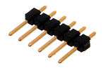


A pin header (often abbreviated as PH, or simply header) is a form of electrical connector. It consists of one or more rows of male pins typically spaced 2.54 millimetres (0.1 in) apart, but 5.08 millimetres (0.2 in), 5.00 millimetres (0.197 in), 3.96 millimetres (0.156 in), 2.00 millimetres (0.079 in), 1.27 millimetres (0.05 in) or 1.00 millimetre (0.04 in) are common as well.[1] The distance between pins is commonly referred as pitch in the electronic community.
In the past, a pin header was known as a Berg connector, but the term fell out of favor because pin headers are manufactured by many companies.
Overview
Pin headers are often associated with ribbon cable connectors, pin headers often also function as recipients for jumpers. The most common jumper spacing is 2.54 millimetres (0.1 in), though 2.0 millimetres (0.079 in) is sometimes used in smaller products.
Pin header connectors are thus "male" connectors ("female" counterparts do exist, but these are normally just called female header (FH) or header connector, without "pin") and are mostly used inside equipment, rather than being used as a connector on the outside of the device.[2]
Normally pin headers are pin through hole (PTH) devices, but surface-mount technology (SMT) versions of one and two row pin headers also exist. In the latter case the solder sides of the pins are simply bent on a 90 degree angle so as to be soldered to a solder plane. On single row pin headers the pins are bent alternating to one side or the other, on dual row pin headers the pins are simply bent outwards. If pin headers are optional, the PTH variant is often chosen for ease of manual assembly. Pin headers can be either straight or angled. The latter form is often used to connect two boards together.
Pin headers are cost-effective due to their simplicity. Headers are often sold as long strips (typically 40 or 50 pins for the dual row versions) which can easily be broken off to the right number of pins.
Shrouded header
Pin headers with a plastic guide box around them are known as box headers (BH) or shrouded headers and are normally only used in combination with insulation-displacement connectors (IDC) for ribbon cables. A notch (key) in the guide box normally prevents placing the connector (polarised by a "bump" on one side) the wrong way around.[3]
Polarizer key
Some systems polarize or key the pin header connection with something that fills and blocks one of the holes in the sockets.[4][5][6][7] One pin of the wrong pin header (or the correct pin header rotated in the wrong orientation) hits that obstruction and prevents an incorrect connection. The correct pin header has one or more pins in the header removed or clipped to indicate a key for correct orientation.
Pin numbering
In absence of a pin 1 designation on the header, if a designation is missing from the header, the PCB may have a marking indicating orientation (often the solder pad around the hole of pin 1 of a PTH header is square rather than round).
For multi-row pin headers, the pin number is more complex, because knowing the location of pin 1 doesn't automatically ensure how the remaining pins are numbered. Typically for headers attached to ribbon cables, the pins are numbered so they go linearly across the cable. Because of the way the connector attaches to the cable, this means in a two-row header, pins in one row have odd numbers and pins in the other row have even numbers.[8]
See also
- Electrical connector
- DC connector
- Insulation-displacement connector (IDC)
- JST connector
- Jumper (computing)
References
- ↑ TSW and HTSW through-hole square post header datasheet; Samtec.
- ↑ Glossary entry about headers; InterfaceBus.com
- ↑ Glossary entry about shrouded headers; InterfaceBus.com
- ↑ "Front panel Connections"
- ↑ "USB 3.0 Header to USB 2.0 Header pinout"
- ↑ "Voided Header Pins and Blanked Socket Cavities"
- ↑ Lee Penrod."How to Install Front USB by Connecting Front USB Ports to a Motherboard". Quote: "One pin is blocked so that it is impossible to install improperly."
- ↑ 10 pin IDC male connector diagram and applications pinouts
External links
| Wikimedia Commons has media related to Pin headers. |
- Examples
- Square Post Header, Male, 0.1-inch center, samtec.com
- Socket Strip, Female, 0.1-inch center, samtec.com
- Shrouded Square Headers, Male, 0.1-inch center, samtec.com